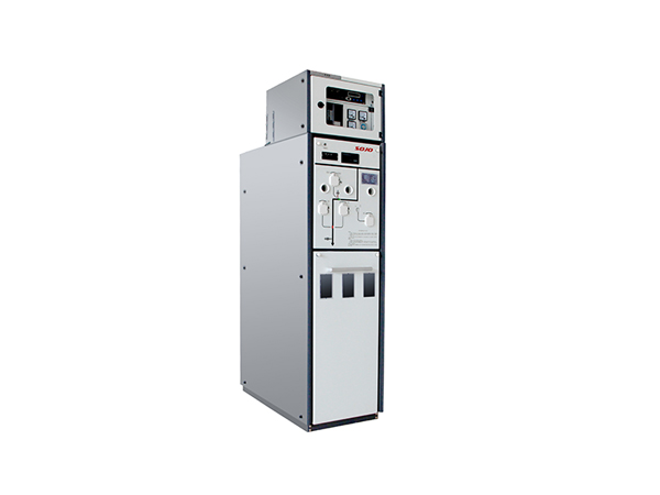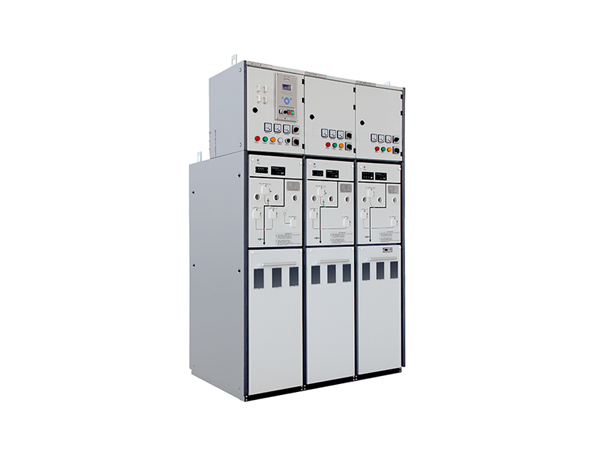
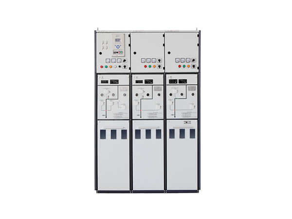
SVI solid insulated switchgear (SF6 free switchgear) is KEMA type tested and suitable for medium voltage power distribution system with a rated voltage of less than 12kV and a rated current under 1250A. It is more reliable than the SF6 ring main unit, and is more suitable for a wider range of applications.
Download:
SOJO SVI solid insulated switchgear.pdf
Application Area
Based on its superior patented technologies such as solid insulation, solid sealed pole, fully-insulated modular busbar, etc, solid insulated ring main unit fully meets the ring network and radiation distribution network of various wiring programs.
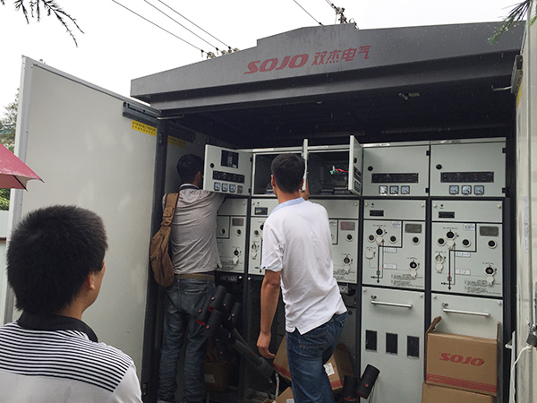
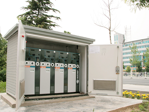
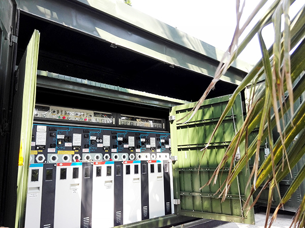
At the same time, solid insulation switch unit has been in the alternative demarcation switch, box-type substation high-side switch, KYN28 in the cabinet, XGN fixed cabinet and other applications have high quality performance, especially for those area which pursues SF6 free.
The intelligent terminal equipment connected to the solid insulated switch unit can monitor and control the real-time situation remotely and ensure the intelligentity, reliability and flexibility of the distribution network system.
Product Features
• Comaring with the gas insulated switchgear, this electrical distribution equipment is SF6 free, no SF6 is contained, avoiding pressure tank designing.
• All live parts are sealed or embedded in the epoxy resin and silicon rubber, fully insulated and wholly enclosed structure, safety protection level: IP67.
• All operating mechanism sealed inside a box, truly maintenance-free.
• Enhanced phase separation design, independent phase insulation to avoid the fault between phases.
• Standard modular design to facilitate unit extension, modification and replacement.
• Switch working position of each phase could be observed independently.
• Safe, smart, environment-friendly, flexible assembly enabled, good performance to apply in special environments.
• Multiple mechanical interlock to achieve 'five-protection' function.
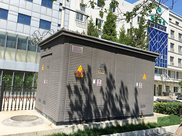
• Complete indoor & outdoor switchgear application solution.
Multi-environment Application

Coastal area: fully sealed structure of the mechanism, professional high salt spray testing equipment to ensure long-term application in coastal areas.
Low temperature area: The solid insulated switchgear doesn't need SF6, so the potential problem caused by insulation gas being liquified under low temperature can be avoided.
Plateau area: Due to the absence of SF6, the problems caused by the big pressure difference between the inside and outside of the gas tank in high altitude areas can be avoided.
Explosion forbidden places: The switch adopts vacuum interrupter sealed with epoxy resin bushing which can prevent the gas exposure and explosion.
Basement with workers: The density of SF6 is 5 times higher than air on the same condition. So if the SF6 in a traditional RMU leaks out, it will accumulate in low area, so the workers there could be harmed or suffocated.
Frequent switching operation situation: Switch operations for solid dielectric designed RMU reaches 20,000 times.
Areas with high requirements for environmental protection: Our solid insulated switchgear doesn’t contain SF6, which is a kind of greenhouse gas.
Windy and sandy area:The IP rating of the live parts reaches IP67. The control circuit compartment is specially treated, so our product can work in windy and sandy area for a long time.
High temperature environment: Suitable for special areas of high temperature environment, the maximum temperature of normal operation is up to 70 ℃. The high temperature environmental test has been performed.
Nominal Working Conditions
Ambient temperature
Maximum temperature + 70℃
Minimum temperature - 50℃
Humidity Level
Maximum comparative average humidity
Daily average ≤ 95%
Monthly average ≤ 90%
Seismic capacity
Level 8
Altitude
≤5500 M
Water submersion test
24 hour water resistance at a pressure of 0.3 bar and voltage of 12 KV.
Degree of protection
Sealed electrified body IP67
Fuse tube IP67
Metal enclosure IP4X
Busbar
Internal earthed busbar 150 mm2Cu
Thickness of insulation bushing 12.0 mm
The diameter of sealed and insulated busbar 28.0 mm
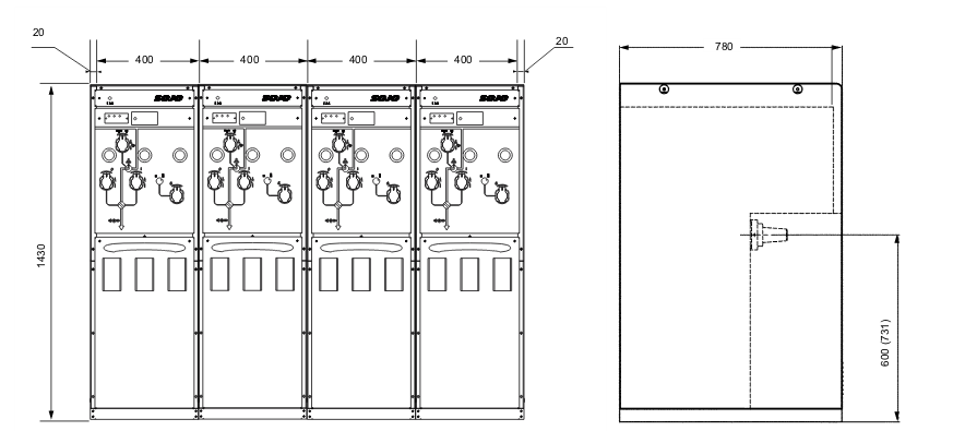
Structure Diagram

Dimensions
| Module C | Module F | Module V | ||||
| Load Switch | Load Switch + Fuse | Vacuum Circuit Breaker | Disconnector | Earthing Switch | ||
| Rated Voltage | kV | 12 | 12 | 12 | 12 | 12 |
| Arc Quenching | Vacuum | Vacuum | Vacuum | |||
| Rated Current | A | 630 | 125 | 630/1250 | 630/1250 | 630/1250 |
| Rated Frequency | Hz | 50 | 50 | 50 | 50 | 50 |
| Main Circuit Resistance | μΩ | ≤120 | 300 Note1 | ≤120 | ||
| Power Frequency Withstand Voltage Between Phases, Phase to earth/open contacts | kV | 42/48 | 42/48 | 42/48 | 42/48 | 42/48 |
| Lightning Impulse Withstand Voltage Between Phases, Phase to earth/open contacts | kV | 75/85 | 75/85 | 75/85 | 75/85 | 75/85 |
Rated Short-circuit Breaking Current |
kA | 31.5 Note2 | 20/25/31.5 | |||
| Rated Short-circuit Breaking Times | times | 30 | ||||
| Rated Short-circuit Making Current | kA | 50 | 50/63 | |||
| Rated Short-circuit Making Times | times | 5 | 5 | |||
| Rated Short-time Withstand Current | kA/4s | 20 | 20/25 | 20/25 | 20/25 | |
| Rated Peak Withstand Current | kA | 50 | 50/63 | 50/63 | 50/63Out | |
| Out-of-phase Earth Fault Breaking Current | kA | 17.3/21.7 | ||||
| Rated Cable Charging Breaking Current | A | 10 | 10 | |||
| Rated Take-over Current | A | |||||
| Internal Arc Test(AFLR) | KA/s | 20KA/0.5s (Include busbar room, switch room, cable tank) | ||||
| Partial Discharge | pC | ≤5 | ≤5 | ≤5 | ||
| IP Rating | IP67 | IP67 | IP67 | |||
| Mechanical Endurance | times | 10000 | 10000 | 10000 | 3000 | 3000 |