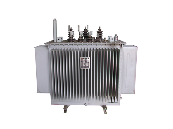
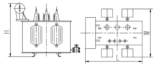
The oil immersed power transformer is composed of core, coil, voltage regulating switch, oil tank and other components, and the dielectric material is dielectric oil.
Download:
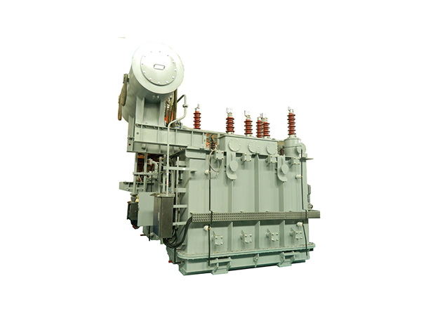
The oil immersed power transformer is used for regulating voltage and AC power transmission. The advantages include small dimension, reasonable price, strong weather resistance and so on. It is applicable to power systems, industrial and mining enterprises, transportation, post and telecommunications sector, research institutes, etc. A variety of transformers under 110kV are included in the product line: the stacked iron core structure series, the rolled iron core structure series, amorphous alloy series, etc. Smart and diverse structures and nice appearance make this product to meet the needs of different users.
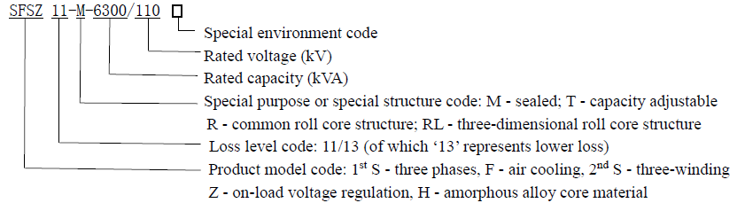
Model Explaination
Features:
Core
High-quality grain-oriented cold-rolled silicon steel sheet are employed, and the whole oblique non-porous banding structure are used here. The core has a multi-level ladder shape, with three joints or five joints, which is of low no-load loss and low noise. Rolled cores are direct rolled by certain special equipment, which gives the advantages including no seam, no corner weight, reluctance reduction, low no-load loss. Amorphous alloy is an advanced core material, which leads to an average reduction of 72% no-load loss and a reduction of 50% no-load current.
Coil
The high-quality QQ acetal enameled round copper wire and oxygen-free copper rod are used to form the coil. The coil type includes cylinder type, continuous type, new type spiral type, split type, etc. It has sufficient electrical strength, mechanical strength and cooling capacity.
In order to increase the capacity of anti-short-circuit of the transformer, self-adhesive transposition wire is used in the 35kV and above windings. The wire is made of self-adhesive acetal enameled flat wire, and after winding into a coil, it is heated so that the flat wire could be bonded between each other to form a rigid coil, which can withstand greater bending stress, thereby enhancing the capacity of anti-short-circuit of the transformer. The most important feature of the self-adhesive transposition wire is that it can reduce the loss of the transformer, and as a result of multi-stranded conductor with transposition, the eddy current loss and circulation loss are greatly reduced, it can also reduce the temperature rise of the partial hot spots of winding, thus the winding temperature distribution is more uniform.
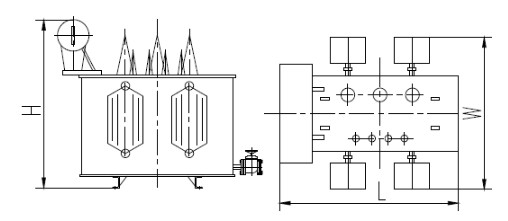
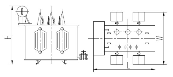
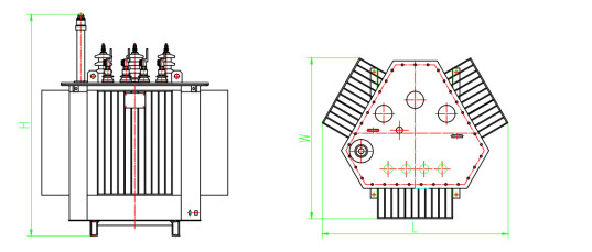
Oil tank
The oil tank is made of high quality steel plate, and the shape includes elliptical shape, rectangular shape, etc. The type of the radiator includes: corrugated sheet type radiator, expansion type radiator and corrugated type tank. The sealing performance test is conducted on oil tanks. The inside and outside surfaces are pickling and phosphate treated, and then spray priming paint for three times and surface paint for one time, which give its corrosion resistance.
Normal service condition
Ambient air temperature
Maximum temperature: +40℃
Minimum temperature: -45℃
Average temperature of the warmest month: +30℃
The hottest annual average temperature: +20℃
Altitude: ≤ 1000m
Contamination class: III;
Seismic intensity: VIII
Power supply voltage waveform: approximately sinusoidal;
Note: If the above conditions are exceeded, please specify when ordering, for special consideration.
1、S11 10kV Three Phase Oil Immersed Natural Air Cooling Double Winding Off Circuit Tap Changing Distribution Transformer
| Model | Rated Capacity(kVA) | Voltage (kV) | Vector Group | Impedance Voltage(%) | Total Weight(t) | Reference Dimensions(mm) L*W*H |
No-load Loss (W) | Load Loss (W) |
| S11-30/10 | 30 | High Voltage H.V. 6,6.3,10,10.5 ±2×2.5% ±5% Low Voltage L.V. 0.4 |
Dyn11 Yyn0 |
4 | 0.35 | 720*480*850 | 100 | 630/600 |
| S11-50/10 | 50 | 0.4 | 750*500*900 | 130 | 910/870 | |||
| S11-63/10 | 63 | 0.5 | 800*600*950 | 150 | 1090/1040 | |||
| S11-80/10 | 80 | 0.55 | 1000*720*980 | 180 | 1310/1250 | |||
| S11-100/10 | 100 | 0.6 | 1050*750*1000 | 200 | 1580/1500 | |||
| S11-125/10 | 125 | 0.7 | 1100*760*1050 | 240 | 1890/1800 | |||
| S11-160/10 | 160 | 0.75 | 1120*770*1070 | 280 | 2310/2200 | |||
| S11-200/10 | 200 | 0.8 | 1150*800*1100 | 340 | 2730/2600 | |||
| S11-250/10 | 250 | 1 | 1300*950*1100 | 400 | 3200/3050 | |||
| S11-315/10 | 315 | 1.2 | 1400*1000*1100 | 480 | 3830/3650 | |||
| S11-400/10 | 400 | 1.4 | 1400*1000*1200 | 570 | 4520/4300 | |||
| S11-500/10 | 500 | 2 | 1700*1200*1400 | 680 | 5410/5150 | |||
| S11-630/10 | 630 | 4.5 | 2.5 | 1800*1300*1500 | 810 | 6200 | ||
| S11-800/10 | 800 | 2.8 | 2150*1950*2000 | 980 | 7500 | |||
| S11-1000/10 | 1000 | 3.2 | 2200*2000*2050 | 1150 | 10300 | |||
| S11-1250/10 | 1250 | 3.7 | 2300*2100*2100 | 1360 | 12000 | |||
| S11-1600/10 | 1600 | 4.5 | 2400*2200*2200 | 1640 | 14500 | |||
| S11-2000/10 | 2000 | 5 | 5.5 | 2500*2400*2300 | 1940 | 18300 | ||
| S11-2500/10 | 2500 | 6.4 | 2700*2600*2500 | 2290 | 21200 |
2、S13 10kV Three Phase Oil Immersed Natural Air Cooling Double Winding Off Circuit Tap Changing Distribution Transformer
| Model | Rated Capacity(kVA) | Voltage (kV) | Vector Group | Impedance Voltage(%) | Total Weight(t) | Reference Dimensions(mm) L*W*H |
No-load Loss (W) | Load Loss (W) |
| S13-30/10 | 30 | High VoltageH.V. 6,6.3,10,10.5 ±2×2.5% ±5% Low Voltage L.V. 0.4 |
Dyn11 Yyn0 |
4 | 0.35 | 720*480*850 | 80 | 630/600 |
| S13-50/10 | 50 | 0.4 | 750*500*900 | 100 | 910/870 | |||
| S13-63/10 | 63 | 0.5 | 800*600*950 | 110 | 1090/1040 | |||
| S13-80/10 | 80 | 0.55 | 1000*720*980 | 130 | 1310/1250 | |||
| S13-100/10 | 100 | 0.6 | 1050*750*1000 | 150 | 1580/1500 | |||
| S13-125/10 | 125 | 0.7 | 1100*760*1050 | 170 | 1890/1800 | |||
| S13-160/10 | 160 | 0.75 | 1120*770*1070 | 200 | 2310/2200 | |||
| S13-200/10 | 200 | 0.8 | 1150*800*1100 | 240 | 2730/2600 | |||
| S13-250/10 | 250 | 1 | 1300*950*1100 | 290 | 3200/3050 | |||
| S13-315/10 | 315 | 1.2 | 1400*1000*1100 | 340 | 3830/3650 | |||
| S13-400/10 | 400 | 1.4 | 1400*1000*1200 | 410 | 4520/4300 | |||
| S13-500/10 | 500 | 2 | 1700*1200*1400 | 480 | 5410/5150 | |||
| S13-630/10 | 630 | 4.5 | 2.5 | 1800*1300*1500 | 570 | 6200 | ||
| S13-800/10 | 800 | 2.8 | 2150*1950*2000 | 700 | 7500 | |||
| S13-1000/10 | 1000 | 3.2 | 2200*2000*2050 | 830 | 10300 | |||
| S13-1250/10 | 1250 | 3.7 | 2300*2100*2100 | 970 | 12000 | |||
| S13-1600/10 | 1600 | 4.5 | 2400*2200*2200 | 1170 | 14500 | |||
| S13-2000/10 | 2000 | 5 | 5.5 | 2500*2400*2300 | 1390 | 18300 | ||
| S13-2500/10 | 2500 | 6.4 | 2700*2600*2500 | 1650 | 21200 |
3.S13-M.RL 10kV Three Phase Oil Immersed Wound Core Natural Air Cooling Double Winding Off Circuit Tap Changing Distribution Transformer
| Model | Rated Capacity(kVA) | Voltage (kV) | Vector Group | Impedance Voltage(%) | Total Weight(t) | Reference Dimensions(mm) L*W*H |
No-load Loss (W) | Load Loss (W) |
| S13-M.RL-30/10 | 30 | High Voltage H.V. 6,6.3,10,10.5 ±2×2.5% ±5% Low VoltageL.V. 0.4 |
Dyn11 Yyn0 |
4 | 0.35 | 0.8*0.7*0.8 | 80 | 630/600 |
| S13-M.RL -50/10 | 50 | 0.45 | 1*0.85*0.95 | 100 | 910/870 | |||
| S13-M.RL -63/10 | 63 | 0.5 | 1.1*0.8*1.2 | 110 | 1090/1040 | |||
| S13-M.RL -80/10 | 80 | 0.58 | 1.1*0.8*1.35 | 130 | 1310/1250 | |||
| S13-M.RL -100/10 | 100 | 0.65 | 1.1*0.8*1.35 | 150 | 1580/1500 | |||
| S13-M.RL -125/10 | 125 | 0.7 | 1.1*0.85*1.4 | 170 | 1890/1800 | |||
| S13-M.RL -160/10 | 160 | 0.8 | 1.1*0.95*1.42 | 200 | 2310/2200 | |||
| S13-M.RL -200/10 | 200 | 0.95 | 1.15*1*1.5 | 240 | 2730/2600 | |||
| S13-M.RL -250/10 | 250 | 1.1 | 1.2*1.1*1.5 | 290 | 3200/3050 | |||
| S13-M.RL -315/10 | 315 | 1.3 | 1.3*1.12*1.5 | 340 | 3830/3650 | |||
| S13-M.RL -400/10 | 400 | 1.45 | 1.35*1.2*1.55 | 410 | 4520/4300 | |||
| S13-M.RL -500/10 | 500 | 1.9 | 1.5*1.3*1.6 | 480 | 5410/5150 | |||
| S13-M.RL -630/10 | 630 | 4.5 | 2.1 | 1.5*1.3*1.7 | 570 | 6200 | ||
| S13-M.RL -800/10 | 800 | 2.5 | 1.55*1.35*1.75 | 700 | 7500 | |||
| S13-M.RL -1000/10 | 1000 | 3 | 1.75*1.5*1.75 | 830 | 10300 | |||
| S13-M.RL -1250/10 | 1250 | 3.5 | 1.8*1.5*1.9 | 970 | 12000 | |||
| S13-M.RL -1600/10 | 1600 | 4.5 | 1.9*1.7*2 | 1170 | 14500 |
4.SH15 10kV Three Phase Oil Immersed Natural Air Cooling Double Winding Off Circuit Tap Changing Distribution Transformer With Amorphous Alloy Core
| Model | Rated Capacity(kVA) | Voltage (kV) | Vector Group | Impedance Voltage(%) | Total Weight(t) | Reference Dimensions(mm) L*W*H |
No-load Loss (W) | Load Loss (W) |
| SH15-30/10 | 30 | High Voltage H.V. 6,6.3,10,10.5 ±2×2.5% ±5% Low Voltage L.V. 0.4 |
Dyn11 Yyn0 |
4 | 0.4 | 1000*550*700 | 33 | 630/600 |
| SH15-50/10 | 50 | 0.6 | 1100*600*700 | 43 | 910/870 | |||
| SH15-63/10 | 63 | 0.65 | 1100*650*900 | 50 | 1090/1040 | |||
| SH15-80/10 | 80 | 0.7 | 1150*650*900 | 60 | 1310/1250 | |||
| SH15-100/10 | 100 | 0.65 | 1200*700*900 | 75 | 1580/1500 | |||
| SH15-125/10 | 125 | 0.83 | 1250*950*900 | 85 | 1890/1800 | |||
| SH15-160/10 | 160 | 0.9 | 1300*1100*900 | 100 | 2310/2200 | |||
| SH15-200/10 | 200 | 1 | 1400*1000*900 | 120 | 2730/2600 | |||
| SH15-250/10 | 250 | 1.4 | 1600*1100*950 | 140 | 3200/3050 | |||
| SH15-315/10 | 315 | 1.6 | 1700*1100*970 | 170 | 3830/3650 | |||
| SH15-400/10 | 400 | 1.7 | 1750*1100*1000 | 200 | 4520/4300 | |||
| SH15-500/10 | 500 | 2.3 | 1800*1100*1100 | 240 | 5410/5150 | |||
| SH15-630/10 | 630 | 4.5 | 2.6 | 1900*1100*1100 | 320 | 6200 | ||
| SH15-800/10 | 800 | 2.9 | 2000*1500*1200 | 380 | 7500 | |||
| SH15-1000/10 | 1000 | 3.5 | 2100*1600*1350 | 450 | 10300 | |||
| SH15-1250/10 | 1250 | 4.5 | 2200*1700*1350 | 530 | 12000 | |||
| SH15-1600/10 | 1600 | 6 | 2300*1900*1400 | 630 | 14500 | |||
| SH15-2000/10 | 2000 | 7 | 2400*2000*1700 | 750 | 18300 | |||
| SH15-2500/10 | 2500 | 9 | 2550*2500*1700 | 900 | 21200 |